Reference tutorial guide
http://www.wings3d.com/?page_id=252
3D MODELING
In general, 3D modeling describes the process of creating mathematically defined computer graphics using a three dimensional coordinate system.
Types of 3D Modeling
Subdivision Modeling – Wings 3D is a subdivision modeler. Subdivision describe the process of smoothing a polygon model by subdividing each face of a model into four.
NURBS – Nurbs are generally used by CAD modelers. Nurbs are purely mathematically defined shapes. Every curve, edge and surface is defined by mathematical formulae. Nurbs are often used for architectural projects, industrial design, and techincal applications.
Voxels – Voxels are like 3D pixels. Voxel modelers tend to support very high levels of detail.
Rendering
Once a model is finished it can be rendered. Rendering describes the process of using a program to simulate lighting and materials to produce an often realistic image of the model.
Animation and Rigging
Models which are to be animated have to be rigged. Rigging describes the process of setting up a model for animation. Animators will use software to define points of movement and compression in a model. Rigging may be done with bones or mesh deformations, rotations, scaling, and translations.
3D COORDINATE SYSTEM BASICS
3D models are stored using a 3D coordinate system. This page describes some of the more common elements of a coordinate system that you will need to be familiar with when modeling.
Coordinates
Every point of a 3D model is mapped to a location in space measured along X, Y and Z. When taken together, {X,Y,Z} is called a coordinate. Wings 3D uses the Cartesian coordinate system.
Axes XYZ
Looking at the Wings 3D workspace, you can see the red, blue, and green lines that represent the X,Y, and Z axes.
I
n Wings 3D, Y is up and down, X is side to side, and Z is front to back. These three axes are commonly used to define the active axis for moving, scaling, or rotating a model. Often in Wings 3D they will be referred to as
Standard axes.
Note: Other modelers may swap the Y and Z axis, so when importing a model into Wings 3D it may appear to be the wrong way around.
Points
A point is any location in 3D space. Points can be used as references, such as the center around which a model will be rotated. A point may be defined by the intersection of two vectors. Points can also be used to define the location of a plane.
Vectors
A vector is defined by two points. Adding the coordinates of two points results in a vector coordinate including its magnitude.
A vector is generally necessary to establish a direction or axis depending on the context in which the vector is to be used. A vector is often used to define a direction for movement or an axis of rotation.
Normals
An un-normalised vector denotes not just direction but also magnitude. Normalised vectors have a magnitude of 1.0, hence the meaning of normalisation.
Planes
A plane is defined by a minimum of three unique points in space. These points make a triangle, which is the minimum requirement for defining a surface. Once we have these points, they can be added together to determine the plane vector. A plane’s location can be determined by finding the center or average of its defining points. However, if a plane’s vector is normalised, it represents a surface located anywhere in space. A normalised plane will often be used in conjunction with a point to place the plane.
To picture a plane vector, think of a table. The surface of the table represents a plane along which things can move in two directions. The plane vector as represented as a coordinate is actually a vector point straight up or perpendicular to the table’s surface. If we normalise this vector, then we can relocate the surface of the table to any parallel plane in the room. But once the table in rotated, the plane has changed. All parallel planes are represented by the same plane normal.
EDGE LOOPS IN WINGS 3D
Edge Loops

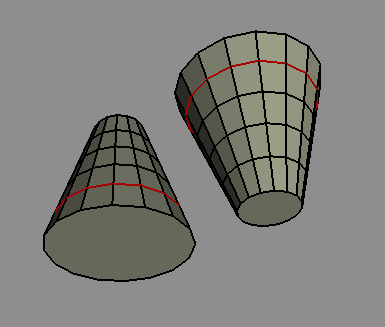
An Edge Loop is a series of connected edges on the surface of an object that runs completely around an object and ends up at the starting point.
The connected edges that encircle a model of an arm, say, are edge loops.
To create an edge loop in Wings 3D, select an edge and [Select | Edge Loop | Edge Loop], or more easily: use the L Hotkey. (‘L’ = Loop).
You can use the F6 and F7 Hotkeys to ‘march up and down’ a chain of edge loops to do rapid model adjustments.
Importantly, an edge loop can only pass ‘straight ahead’ through a 4-way intersection at a vertex. That is, all vertices on an edge loop will have 4 connected edges. If a vertex has more or less than four connected edges it is called a pole. If an edge loop meets a pole – it stops.

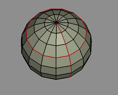
For example, on a sphere object, the longitudinal and latitudinal lines (series of edges) are both types of edge loop.
The latitudinal edge loops continue completely around the sphere – all vertices around the loop are connected to four edges.
The longitudinal edge loops stop at the top and bottom – the vertices at these two points have multiple edges converging there.
Now, a pole in 3D graphics is different to the North and South Poles and they should not be confused, but this example is used to illustrate the point.
But look more closely ….
Edge loops need 4-way intersections at vertices. In Wings 3D, if the number of edges at a vertex is even then the edge loop continues ‘straight ahead’. If the number of edges is odd, then the edge loop halts.

Take a look at the examples here of several ‘sphere’ objects which have been created with 3, 4, … 8 sections, so creating poles with 3, … 8 edges/faces. Note that the longitudinal edge loops traverse the top and bottom vertices that have even number of converging edges, but not the vertices which have odd numbers of edges.
Also note that an edge loop continues if a vertex has only two edges connected, for example, after an edge has been cut.
Odd? A Bug in Version 1.4.1? Well, maybe, but it does illustrate the way that Wings 3D follows the rule that an edge loop goes ‘straight ahead’. This ‘feature’ can be useful when you really do want a loop that circumnavigates your model – which you usually do! – but can be annoying if that’s not what you had intended.
Whether you need complete or partial edge loops depends on what you want to model. It is generally a ‘good idea’ to avoid having poles, which arise when faces are triangles rather than quads. This is because it can cause problems with smoothing, for example, and also when exporting models to other 3D packages.
Edge Rings

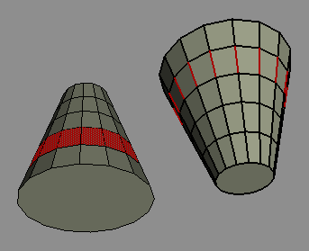
An edge ring is a series of edges connecting two adjacent edge loops. Usually the edges making up the edge ring are at right angles to the edge loops, but it depends on the topology and whether or not the edge loops are parallel.
To create an edge ring, select an edge that is part of the ring you want, and [Select | Edge Loop | Edge Ring], or more easily: use the G Hotkey. (‘G’ = rinG). Switching to face selection mode at this point will highlight the ring of faces around the object between the edge loops. If the edge loops are not complete then the edge ring will stop.
Note that if you switch to face mode after selecting a single edge ring then the adjacent faces are selected (a double ring) and that may not be what you intended.
Optionally, you can select the second, third, Nth edge in the series along the edge ring.
Loop Cut
When an edge loop is selected, the [Edge | Loop Cut] command allows you to split an object along an edge loop into separate parts, which become two new objects. Each part/new object can then be worked on separately and deleted or replicated, moved, scaled, etc.
The Central Edge Loop
This is an edge loop that runs entirely around the long axis of your model.
The central edge loop is important if you want to use Mirror or Virtual Mirror to speed up your modeling. If you maintain your central edge loop, then you will be able to model on one half of the model, Loop Cut off the other half, and then Mirror, which will cut your modeling time in half.
Good maintenance of the central loop means you should keep the edges straight and to not have it interrupted by poles.
The first point is an absolute requirement, or very strange things will happen when you Mirror.
You can work around the second point. If when you go to select the loop it only partially encircles your model because of pole interruptions, you can manually select other parts to get a full loop for the Loop Cut operation.
 Design